Support and LCM of Network Slice Services
Support and LCM of Network Slice Services
Support and LCM of Network Slice Services
Service Exposure Level of Patras5G
See next section about the Exposure Level definition.
The Patras5G exposes all Levels under different circumstances and requirements. This depends on the customer use cases and needs.
Level 1 Access
Exposed entity and access: 5G-VINNI Portal (WEB UI and REST API) https://patras5g.eu , VPN access to deployed NS
Description: Service Catalog exposure (TMForum), Service Ordering Support(TMForum), scheduled orchestration, and VPN access to deployed NS. Access to monitoring data of various points
Level 2 Access
Exposed entity and access: 5G-VINNI Portal (WEB UI and REST API) https://patras5g.eu NFVO onboarding. Will be available at the level of 5G-RAN, 5G-CORE and Transport Controllers
Description: Upload/manage 3rd party VNFs/NSDs to facility NFVO (via web UI and REST API). scheduled NSD orchestration, Depending on the capabilities and if the underlying technologies allow this
Level 3 Access
Exposed entity and access: Access to facility OSM (web and NBI SOL005)
Description: This will be available in special cases where the portal access is not enough. In most cases a separate tenant will be created ( OSM SIX )
Level 4 Access
Exposed entity and access: Access to facility NFVI
Description: Use of Openstack (Rocky) APIs and HORIZON UI. Tenant will not have administrative privileges. Allowed to install VMs on subnets accessible by the 5G core. In certain cases will be allowed to view VNFs deployed by the OSM tenant project
Service exposure, monitoring and testing definition
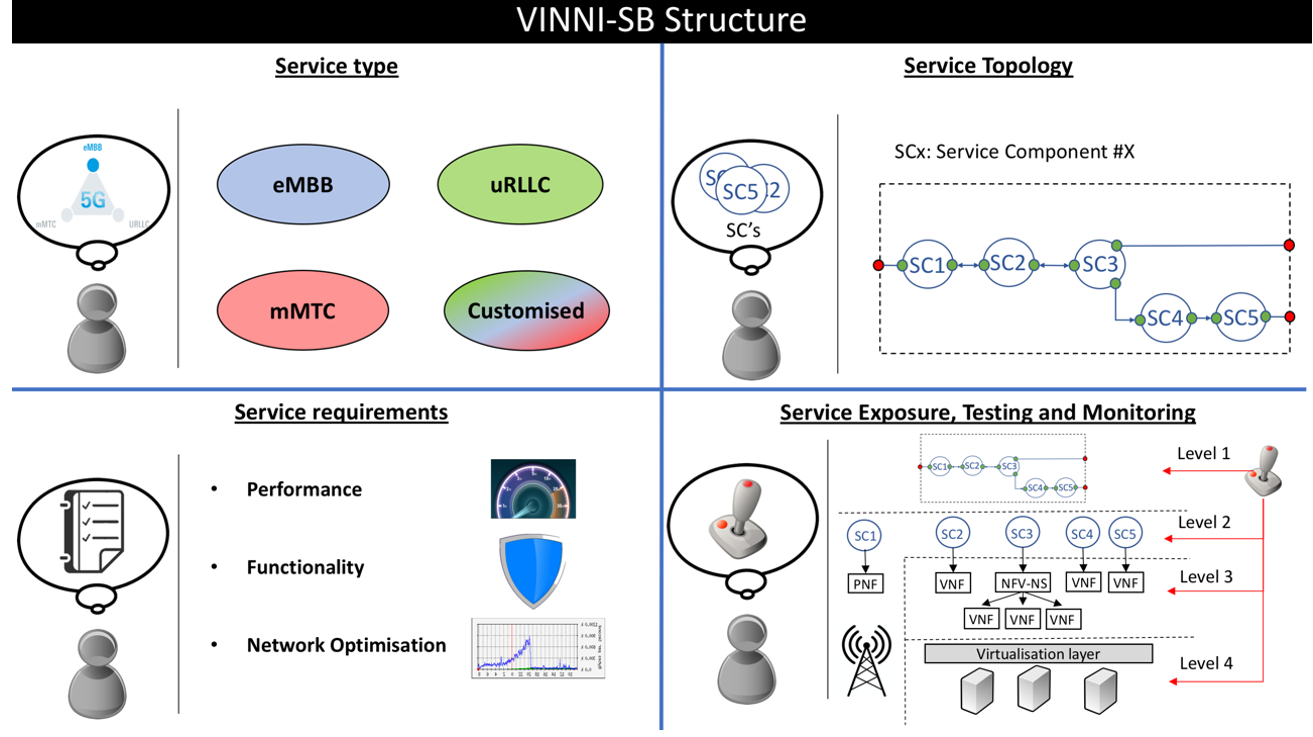
CSP will expose a number of VINNI-SBs towards CSCs. These VINNI-SBs represents service offerings against which CSCs can issue service orders for the delivery of network slice services. The structure of any VINNI-SB is extensively discussed in Deliverable 3.1 of 5G-VINNI project As shown in Figure, VINNI-SB consists of four main parts:
• Service type: provides a high-level description of the slice service to be provided from this VINNI-SB. Any VINNI-SB must specify one of the following options: enhanced Mobile Broadband (eMBB), ultra-Reliable Low Latency Communication (uRLLC), massive IoT (mIoT) and customised.
• Service topology: specifies the functional nodes of the slices and their associated topology. Each of this functional node is referred to as a Service Component (SC), each being a unified abstraction of a given network functionality. SCs are technology-agnostic, modular, and can be easily chained to form different topologies, being these topologies flexibly extended (or even modified) with the attachment of 3rd party VNFs. The topology presented in a VINNI-SB and its possibilities of extension (or even modification) are highly dependent on the service type the VINNI-SB refers to.
• Service requirements: specifies the requirements of the slice service to be provided from the VINNI-SB. These requirements include i) performance requirements, ii) functional requirements and iii) network optimisation requirements. The requirements presented in a VINNI-SB are highly dependent on the service type the VINNI-SB refers to.
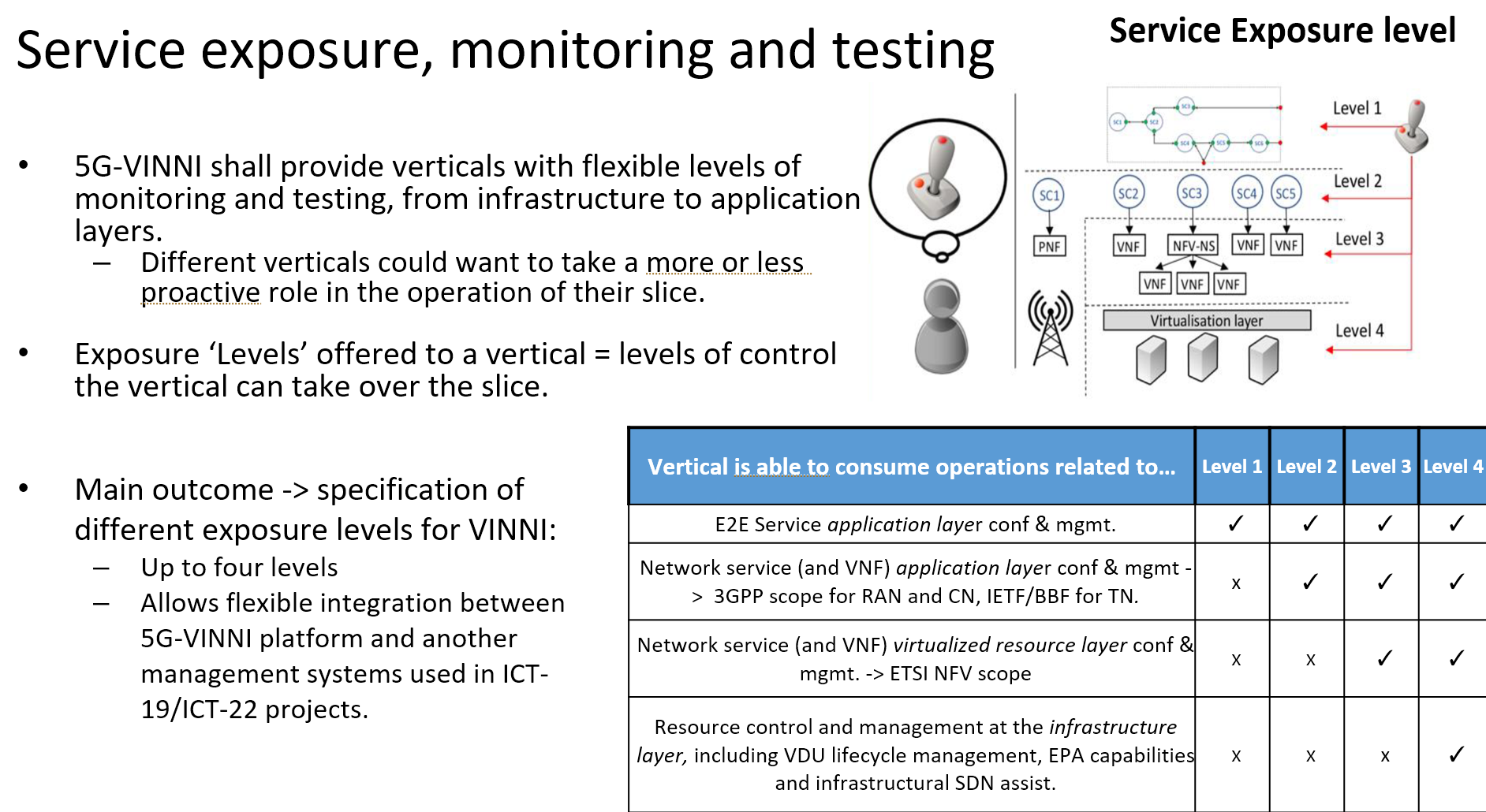
Service exposure, monitoring and testing: specifies the service capability exposure made available to the CSC. This exposure is based on a four-level classification, with each higher level allowing the CSC to gain access to a lower abstraction management entity. Depending on the selected level, the CSC can consume management data (e.g. performance measurements, fault data) and trigger enabled management operations (e.g. LCM) at different abstraction layers, which is relevant for testing and monitoring activities conducted at run-time.
Service exposure, monitoring and testing
The facility is based on OSM. For 5G-VINNI Rel-0 what Greece will offer is based on OSM Release FIVE, while for 5G-VINNI Rel-1 (after Jan 2020) a migration to OSM Release SIX is planned. which brings advancements in monitoring. The VINNI-SB structure is expected for next releases of 5G-VINNI project, after Rel-1. So, for Rel-1 only a subset of the parameters will be available for vertical specification.
OSM software stack allows the deployment and operation of a wide variety of NFV-NSs, and their offering towards OSM clients following the Network as a Service (NaaS) delivery model. This model allows an OSM clients to request the instantiation of one or more NFV-NSs, by selecting the appropriate NSD(s) - elaborated at design time - and providing (missing) instance-specific parameters. The result is one or more NFV-NS instances that the OSM client can consume for its own purposes. This is the way OSM has traditionally worked up to Release FOUR, e.g. in 5GinFIRE project.
However, 5G-VINNI project is committed to go beyond NFV approach, introducing the network slicing concept and make it available to CSC, allowing them to take the role of OSM clients. For this end, the OSM release FIVE has extended the information model from previous releases. This new model introduces the network slice information element following the conceptual outline suggested in ETSI NFV-EVE 012.
OSM Network Slicing
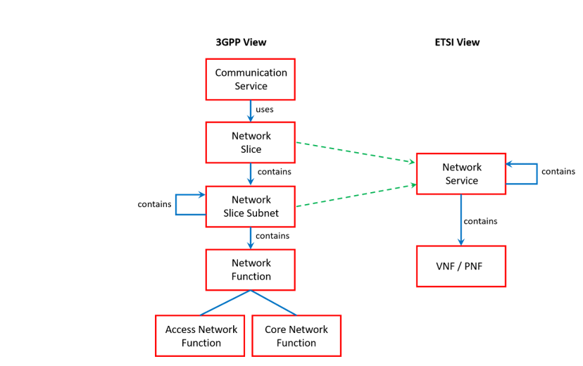
This figure shows that an NFV-NSs can be viewed as the resource-centric view of a network slice subnet, and these network slice subnets can be flexibly combined to build out different (E2E) network slices. According to this approach, in OSM a Network Slice Instance (NSI) will be composed of one or more Network Slice Subnet Instances (NSSIs), each deployed as an instance from a given NFV-NS. For the management of these NSIs, the OSM has extended the NBI component with the incorporation of a module Slice Manager.
Once deployed and operative, NSIs can be delivered to corresponding OSM clients following the NSaaS model, allowing customers to build on top their own services and carry out experimentation activities on the infrastructures. This delivery implies the definition of an appropriate exposure level, according to the requirements set by each OSM client and its networking expertise. Different exposure levels mean that the OSM client is allowed to consume management data at different abstraction levels, and to reach management blocks placed at different abstraction layers to trigger LCM operations.
Supported Network Slice Service Modelling approaches
OSM release FIVE will allow NOP to deploy and operate NSIs and make them available to the CSP. The CSP will be in charge of delivering these NSIs to the CSCs following the NSaaS (see Deliverable D3.1) model. This service delivery model can be described as a particularization of the NSaaS model, but more focused on the enablement of 5G use cases. The evolution from NSaaS (up to OSM release FOUR) to NSaaS (from OSM release FIVE onwards) requires the definition of a single unified framework where the views on network slicing from both 3GPP and ETSI NFV can coexist.
- On one hand, 3GPP deals with the network slicing concept from a functional viewpoint, focusing on NSI application layer management. Examples of issues addressed under this vision are the study of what specific RAN/CN functions make up an NSI at both UP and CP, how these functions communicate with each other via normative (service-based) interfaces, and the implications their sharing brings in terms of isolation and customization.
- On the other hand, ETSI NFV studies network slicing from a deployment viewpoint, focusing on NSI virtualized resource management. This vision study how the flexible allocation of VNFs and their dynamic composition into NFV-NSs can support the resource requirements of an NSI.
As seen from the above description, these views are complementary and need to interact with each other. Indeed, slicing without 3GPP vision is simply an application-agnostic NFV deployment, without any notions on the semantics that allow NFV-NSs to behave as desired. Conversely, slicing without NFV vision does not enable flexibility and agility in network slicing run-time operation, or dynamic provision of resources where and when required. To align these views, OSM release FIVE has proposed the unified conceptual framework shown in Figure 6.14, highly inspired by the ETSI NFV-EVE 012 [EVE012] proposal. The resulting framework allows the NOP to cope with the network slice concept and define a consistent information model that can be used for the design and instantiation of network slices.
Please refer to Annex H.1 on how the OSM framework allows the definition of an information model for network slicing in 5G
Supported Network Slice Service Specification approaches
This section will focus on CSP and CSC roles. The CSP role will be taken by Patras facility site. The VINNI-SBs offered by Patras/Greek CSP in their service catalogues will be based on the structure shown in first Figure. For network slice service specification, the CSC selects the corresponding VINNI-SB (e.g. eMBB/uRLLC/mIoT/customised VINNI-SB) and fills it according to its particular service order requirements, resulting in a Service Order. Stored by the CSP, this Service Order provides a self-contained specification of the network slice service instance for that CSC.
Once a CSC specifies the service as desired and clicks the “Submit service order”, a new VINNI- Service Order Request is created out of the VINNI-SB. Stored by the CSP, this request provides a self-contained specification of the network slice service ordered by that CSC.
Provisioning of network slice instances
The provisioning of NSIs can be described throughout their lifecycle. The lifecycle management process network slicing is originally presented in 3GPP TS 28.530 [3GPP28.530].
The lifecycle management of NSIs carried out by Greeek NOP is compliant with this 3GPP view, thanks to the conceptual outline the OSM information model. In the next subsections, each phase will be discussed individually.
Preparation phase
This phase begins when CSP receives a service order from the CSC. At that moment, a VINNI-SD is created out of VINNI-SB and stored in OSM repository. Then, CSP checks if that VINNI-SD is feasible (e.g. check if all the mandatory parameters have been specified, if there is enough capacity, etc.), and if so, sends corresponding network slice requirements to NOP. With these requirements, the NOP carries out a set of operations arranged into sub-phases: NST design and NST on-boarding.
For the first sub-phase, the NOP takes the received requirements and translates them into the following tuple: {required NST, instantiation parameters}, so NOP can deploy the NSI when and where required. For the preparation phase, only the first field of this tuple is relevant. The required NST shall follow the information model introduced at the beginning of Section 4 and shown in Annex A. This NST can already exist (pre-defined NST, designed beforehand) or not (NST created on demand) in the service catalogue. To handle these two scenarios, two operations are made available to NOP through NST management interface (Section 3):
- nst-create: allows designing an NST from scratch. This operation is triggered by the NOP when there is no pre-defined NST that can be reused for the definition of the required NST.
- nst-update: allows modifying some fields from a given NST. This operation is triggered when the required NST can be obtained by updating some of the content of an already existing NST.
Either of the abovementioned options allows NOP to have the required NST designed, and thus the first sub-phase completed. From that moment onwards, the NST is on-boarding can get started.
In this second sub-phase, the NOP aims at injecting the required NST into the service catalogue. This process not only consists in on-boarding the NST itself, but also the NFV-NS and VNF Packages referred by the NST (see information model in Annex A). OSM’s NBI offers APIs that support CRUD (Create, Read, Updated, Delete) operations to handle these NFV-NS and VNF packages (and their contained NSDs and VNFDs). In these operations, the necessity checks to validate in-model and cross-model consistency are performed. These API calls are implemented over the NFV-NS/VNF Package management interfaces and the NSD/VNFD management interfaces described in Section 3.
Once the on-boarding process finishes, the NST is stored in the service catalogue, so it can be used for NSI creation later on. At this moment, the NOP can invoke two operations from NST management interface (section 3): - nst-list: allows listing NSTs available in the service catalogue.
- nst-show: allows showing the content of a given NST.
When the NOP finishes invoke either of the two operations, the preparation phase gets finished.
Commissioning phase
Once the NST and corresponding NS/VNF Packages have successfully been on-boarded in the service catalogue, they can be used as deployment templates for the actual NSI deployment. Alike the preparation phase, the commissioning of the NSI from the NST is a phase that can be split into two sub-phases: network slice instantiation and NSI configuration.
Network slice instantiation consists of the day-0 operations that allows creating an NSI where all the components are instantiated. These operations are defined at all the abstraction levels, ranging from VDU level (e.g. VNF component) to network slice level, and are invoked using the VNF, NFV-NS and network slice lifecycle management interfaces described in Section 3. To trigger the instantiation of a network slice, the NOP will consume the nsi-create operation from the network slice lifecycle management interface.
For nsi-create operation, the two fields of the tuple {required NST, instantiation parameters} that was derived in the preparation phase is now needed. A brief overview of the steps that OSM takes when this operation is invoked is shown below:
- First, the NOP analyses the content of the NST and decompose it into its constituents: network slice subnets and virtual links connecting them.
- Secondly, for each network slice subnet, the corresponding NSSI is created. This NSSI is an NFV-NS instance. For the deployment of this NFV-NS instance, the following information is considered:
a) Instantiation parameters: from the tuple {NST, instantiation parameters} derived in the preparation phase. The NOP extracts from these parameters the requirements that are relevant for the network slice subnet to be instantiated.
b) NSD information element: from the IM of the required NST (see Annex A). This information element points to the NSD that will be used for deploying the NFV-NS instance. This instance can be deployed in various forms (e.g. with different topologies, with different capacity) and with different deployment constraints considering the above instantiation parameters, by using the mechanisms that NSD has for that end (e.g. flavoring, affinity/anti-affinity rules, etc).
c) Iss-shared-nss information element: from the IM of the required NST (see Annex A). This information element specifies if the above NSD can be shared or not. If this information element set to YES, and if an already NFV-NS instance provides similar capabilities to those needed by the NSSI, then that NFV-NS instance can be associated with the NSSI. Otherwise, a new NFV-NS instance needs to be deployed. - Thirdly, for each virtual link providing inter-NSSI connectivity, the corresponding virtual link instance is created. For the deployment of this virtual link, the following information is considered:
a) Instantiation parameters: from the tuple {NST, instantiation parameters} derived in the preparation phase. The NOP extracts from these parameters the requirements that are relevant for the virtual link to be instantiated.
b) VLD information element: from the IM of the required NST (see Annex A). This information element points to the VLD that will be used for deploying the NFV-NS instance. This instance can be deployed in various forms (e.g. with different QoS parameters) considering the above instantiation parameters, by using the mechanisms that VLD has for that end (e.g. flavoring).
With the abovementioned steps, the NSI is already created, although not configured.
To start the configuration process, day-1 operations are required at the NSI components. Typical day-1 operations include model-driven interaction with (Virtual/Physical/Hybrid)NFs through the use of Juju charms, which allow NEPs to encapsulate their configuration mechanisms (e.g. YANG/NETCONF, Ansible, SSH+scripts). For (V/P/H)NF application layer configuration, two different kinds of Juju charms can be used: native charms and proxy charms. A brief comparison of these two Juju charms:.
Native charm vs proxy charm
Native: Juju charm used for those NFs that are able to run charms inside, e.g. cloud-like VNFs. NF interaction happens directly from the orchestrator
Proxy: Juju charm used for those NFs that do not support running charms inside, e.g. PNFs. Proxy charm uses the appropriate configuration protocol to interact with the NF and run the desired actions from the primitive
Operation phase
Once the NSI has been successfully commissioned, the NSI becomes a relevant object for further operation actions. Unlike 3GPP view, operation phase in OSM includes deactivation/activation (e.g. pausing/resuming) as part of the set of modification operations that can be triggered at run-time, depending on the outcomes resulting from the supervision and reporting activities carried out over the NSI throughout its lifetime.
Examples of basic supervising and reporting activities that the NOP can conduct over the NSI are allowed through the following operations, all exposed in the network slice lifecycle management interface:
- nsi-list: list of all operative NSIs
- nsi-op-list: show the history of operations that has been triggered over the NSI since its creation.
- nsi-op-list: shows the information of the operation over a NSI
- nsi-show: shows the record of the NSI
Other more sophisticated activities can be performed, assisted by the MON module, or by the Bugzilla
Depending on the information received from these supervision and reporting activities, the running NSI might need to be modified, in order to keep it in the desired state. For this end, the NOP can trigger a wide variety of day-2 operations over that NSI. These API-driven operations are quite aligned with the specificities indicated by the CSC in the VINNI-SD, and can fall into one of these categories: - Operations at the virtualized resource level: includes operations that has a direct impact on the virtualized resources supporting the NSI. Examples of these operations include scaling operations (e.g. subjected to upper and lower thresholds), creation and deletion of performance measurement jobs, subscribe and notify operations for performance metrics and fault alarms, instantiation and termination of testing components to complete test campaigns, etc. Depending on the service exposure level selected by CSC , these operations can be performed at different abstraction levels, e.g. ranging from NSI level to VNF instance levels.
- Operations at the application level: includes operations that are relevant only for the specific functionality that the NSI offers. Examples of these operations include the addition, modification and deletion of new subscribers, changes in security parameters, changes in routing across the service chain, etc. Those actions need to be enumerated and codified in the constituent NFV-NS Packages the NST refers to and are exposed by the API as primary actions available in that given NSI.
Decommissioning phase
As any other (on-demand) instance of a manageable entity, it is possible to decommission an NSI. This decommissioning means removing all the dedicated components and releasing their underlying resources, but not the shared and dependent components. For those components, they need to be re-configured and their resources should be adjusted accordingly. To illustrate this scenario, consider the case where a NSSI from the NSI that needs to be decommissioned was deployed using a running NFV-NS instance (e.g. a NFV-NS instance also serving other NSSI from another NSI). In such a case, where the NSSI from the NSI to be decommissioned is removed, the NFV-NS instance cannot be removed. Otherwise, the other running NSSI will be affected. To avoid this, when removing the required NSSI, the NFV-NS instance will be re-configured (e.g. disassociated from the removed NSSI) and scale-in accordingly.
As seen again, the lifecycle management of NSSI and NFV-instances, although dependent, are separate.
For the decommissioning phase, Spanish and Greek NOPs may invoke the nsi-delete operation through the network slice LCM interface.